

A sensor wire chafes through on a chassis bracket, touches the body, and the ECU has a few milliseconds to decide whether it is looking at a real signal, a short to ground or a broken sensor. If that decision was never tested on the bench, it will be tested in the field. Fault injection is how you move that test back to the lab: you deliberately create the electrical faults a harness will one day suffer, in a controlled and repeatable way, and you check that the ECU detects them, reports the right diagnostic code and falls back to the right degraded mode, without being damaged.
This guide explains the fault types, how a switching matrix is built, how to size it, how to keep the setup safe, and how to make every injected fault traceable.
1. The fault types you need to cover
Most electrical fault campaigns start from five basic faults, applied to each relevant pin:
- Open circuit: the line is disconnected between harness and ECU. It simulates a broken wire, a backed-out contact or an unplugged connector.
- Short to ground: the line is tied to the ground reference. It simulates insulation damage against the body or chassis.
- Short to battery: the line is tied to the supply rail. It simulates chafing against a powered conductor.
- Pin-to-pin short: two signal lines are connected together. It simulates damage inside a bundle or a contamination bridge in a connector.
- Series or parallel resistance: a resistor is inserted in series (corroded contact, degraded crimp) or in parallel to ground or supply (leakage, moisture). These “soft” faults are often the most interesting, because they sit close to the ECU’s detection thresholds.
For each pin, the test specification should state which faults apply. A short to battery on an output that is already driven high may be pointless; an open circuit on a redundant ground may be the most important test of the whole campaign.
2. How a fault-injection matrix works
2.1 Principle diagram (described)
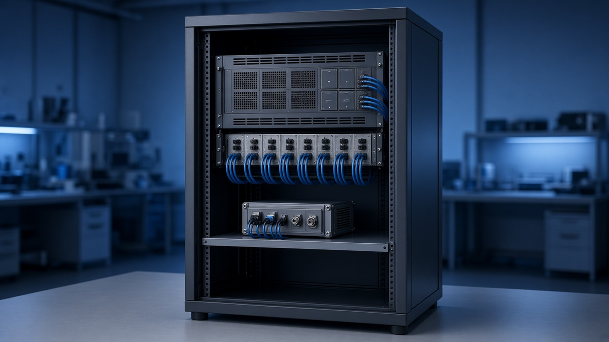
The fault-injection unit sits between the harness and the ECU under test, in series with every line you want to disturb. Picture it from left to right:
- The vehicle or bench harness arrives on connector A.
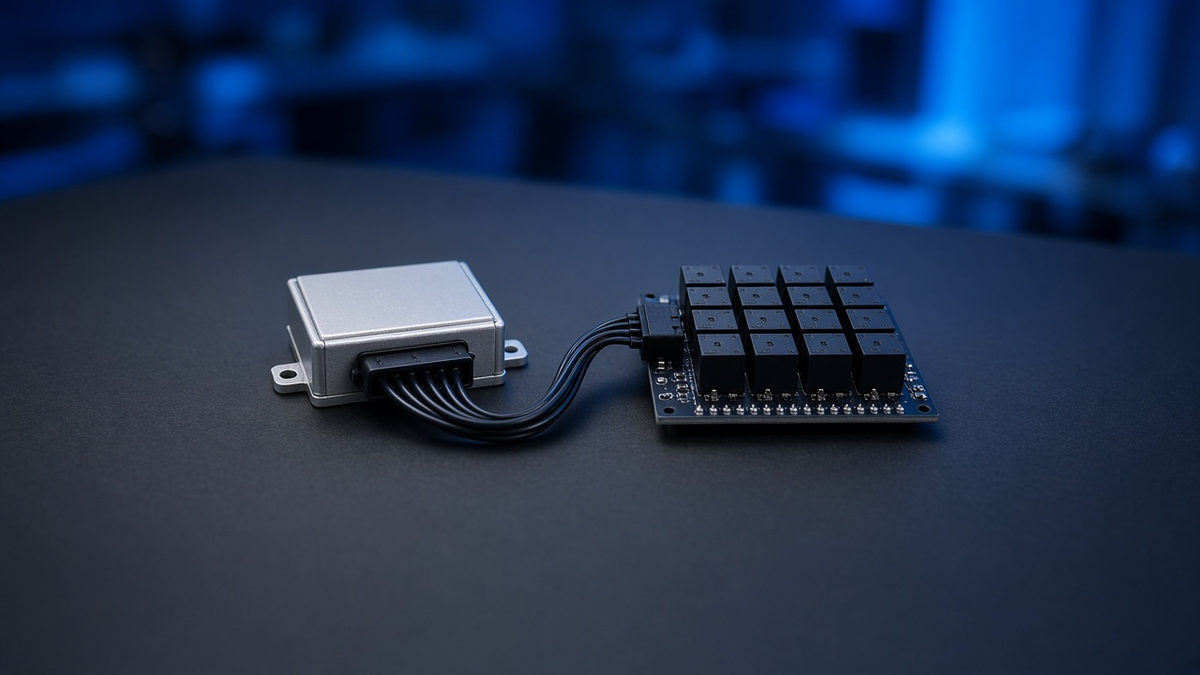
- Each line passes through a series relay (normally closed path). Opening it creates the open circuit.
- On the ECU side of that relay, each line can be connected through further relays to one of several fault buses: a ground bus, a battery bus, and a “pin-to-pin” bus shared by lines.
- A resistor decade or selectable resistor bank can be switched into the series path or between the line and a fault bus to create resistive faults.
- The line leaves on connector B toward the ECU.
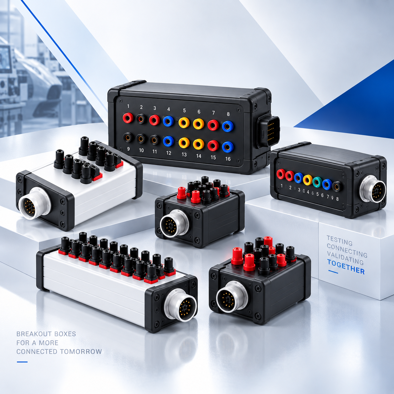
A test sequencer drives the relays, so each fault is a defined state of the matrix. In practice, the fault-injection unit is often combined with a breakout box so that every line also remains accessible for measurement.
2.2 Why a shared fault bus is a design decision
A shared bus keeps the relay count manageable: with N lines, you need roughly one series relay plus one or two bus relays per line, rather than a relay for every possible pair. The trade-off is that only one fault (or one pair) can be active on a bus at a time. If your specification requires simultaneous independent faults, plan several buses.
3. Sizing the relays and the paths
The relay must survive the worst case it can see, not the nominal current.
3.1 Selection criteria
- Continuous current of the line in normal operation (series path).
- Fault current when you short a line to ground or battery. This is set by the source impedance and any limiting you add, not by the ECU.
- Switching voltage and whether the relay switches under load (contact wear, arcing on inductive loads).
- Contact resistance, which adds to the line and matters for low-level analog signals and sensor grounds.
- DC breaking capacity: relay contacts are rated much lower in DC than in AC; check the DC switching curve at the line voltage, especially on inductive loads, and prefer switching the fault with no current where possible (contact welding risk).
- Signal type: for low-level analog or communication lines, check capacitance and leakage of the path too.
3.2 Worked example (illustrative values, not RAYNOV specifications)
Example: a low-side ECU output, switched on (line held close to 0 V), and you inject a short to battery through a 10 Ω current-limiting resistor. The current is roughly I = V / R = 12 V / 10 Ω = 1.2 A. The resistor dissipates P = V² / R = 144 / 10 = 14.4 W while the fault is active. A 0.25 W resistor would fail immediately; a power resistor, a short fault duration, or a higher resistance is needed. The ECU driver must also be rated, or protected, for that current.
Example: on a sensor ground carrying 50 mA, a relay contact of 100 mΩ adds a drop of 0.05 A × 0.1 Ω = 5 mV. On a ratiometric sensor with a few millivolts of resolution, that is not negligible. Count every contact, connector and wire segment in the path.
4. Safety: protect the ECU, the bench and the operator
Fault injection is deliberately destructive in intent, so the setup must limit the damage to what you actually want to test.
- Current limiting on the battery and ground fault buses: a resistor, an electronic limit on the power supply, or both.
- Fuses on fault buses, sized below the rating of the relays and wiring of the matrix.
- Sequencing rule: open before you short. Always break the existing path before connecting a line to a fault bus, and release the fault before closing the series path again. Never rely on two relays changing state “at the same time”.
- Break-before-make behaviour verified on the actual relays, including bounce time.
- Emergency stop that returns the matrix to its neutral state (all series paths closed, all fault buses open) or cuts the supply, depending on what is safest for the ECU.
- Interlocks in software: forbid states that would short battery to ground through two lines.
5. Traceability: one fault, one test line
A fault campaign is only useful if you can prove later what was injected and what happened. Each injected fault should be a test step with:
| Field | Example content |
|---|---|
| Pin / signal | Input X, connector A pin 12 (example) |
| Fault type | Short to ground via 0 Ω |
| Preconditions | Supply voltage, ECU mode, other faults inactive |
| Duration | Time the fault is held |
| Expected response | Diagnostic code, degraded mode, output state |
| Measured response | Read back from the ECU (diagnostic tool) and measured on the line |
| Recovery check | ECU behaviour after the fault is removed |
| Verdict | Pass / fail |
The recovery check is often forgotten. Many ECUs must clear or latch a fault in a defined way after it disappears; that behaviour deserves its own expected result. Test limits and sequences should be versioned, as for any automated test (Test automation: from script to sequencer).
6. The special case of communication buses
Faults on a CAN bus cannot be handled like a simple digital line.
- A CAN bus is a differential pair with terminations. Opening one wire or shorting CAN-H to CAN-L changes the bus, not just one node.
- Inserting relays adds capacitance and stubs; at higher bit rates this can create errors that you did not intend to inject.
- Removing or adding a termination is a fault in its own right and must be modelled explicitly.
- The behaviour depends on the bus load and the other nodes present, real or simulated.
Treat bus faults as a dedicated part of the campaign, with their own hardware and expected results, and check that the matrix itself does not degrade the bus in the “no fault” state.
7. Common mistakes
- Sizing relays for the nominal current and not for the fault current.
- Shorting before opening, which briefly connects the harness source to the fault bus.
- Forgetting the contact resistance of the matrix on low-level sensor lines and grounds.
- Testing only “hard” faults (0 Ω, open) and never the resistive values close to detection thresholds.
- No recovery check after the fault is removed.
- Not validating the matrix itself before the campaign (see the bench qualification approach in Qualifying a test bench before production (FAT/SAT)).
8. Checklist before the first campaign
- [ ] Fault list per pin agreed with the ECU specification
- [ ] Relay ratings checked against fault current and switching voltage
- [ ] Current limiting and fuses on every fault bus
- [ ] Sequencing (open before short) enforced in software
- [ ] Forbidden states blocked by interlocks
- [ ] Emergency stop returns to a safe neutral state
- [ ] Matrix verified in “no fault” state (continuity, contact resistance, bus quality)
- [ ] Each fault = one traceable test line with expected and recovery results
Where fault injection fits in a test bench
Fault injection is usually one building block of a larger bench, together with breakout access, loads, instrumentation and, for closed-loop testing, a real-time model. The architecture of such benches is covered in HIL test benches: architecture, components and implementation steps. RAYNOV designs and builds this kind of equipment as part of its custom validation system delivery, and the way acceptance tests are written for it is described in our article ATP vs QTP.
Further reading
- CAN in Automation (CiA), CAN knowledge: physical layer, terminations and bus behaviour.
Planning a fault-injection campaign or a matrix for your ECU? Tell us about your project.