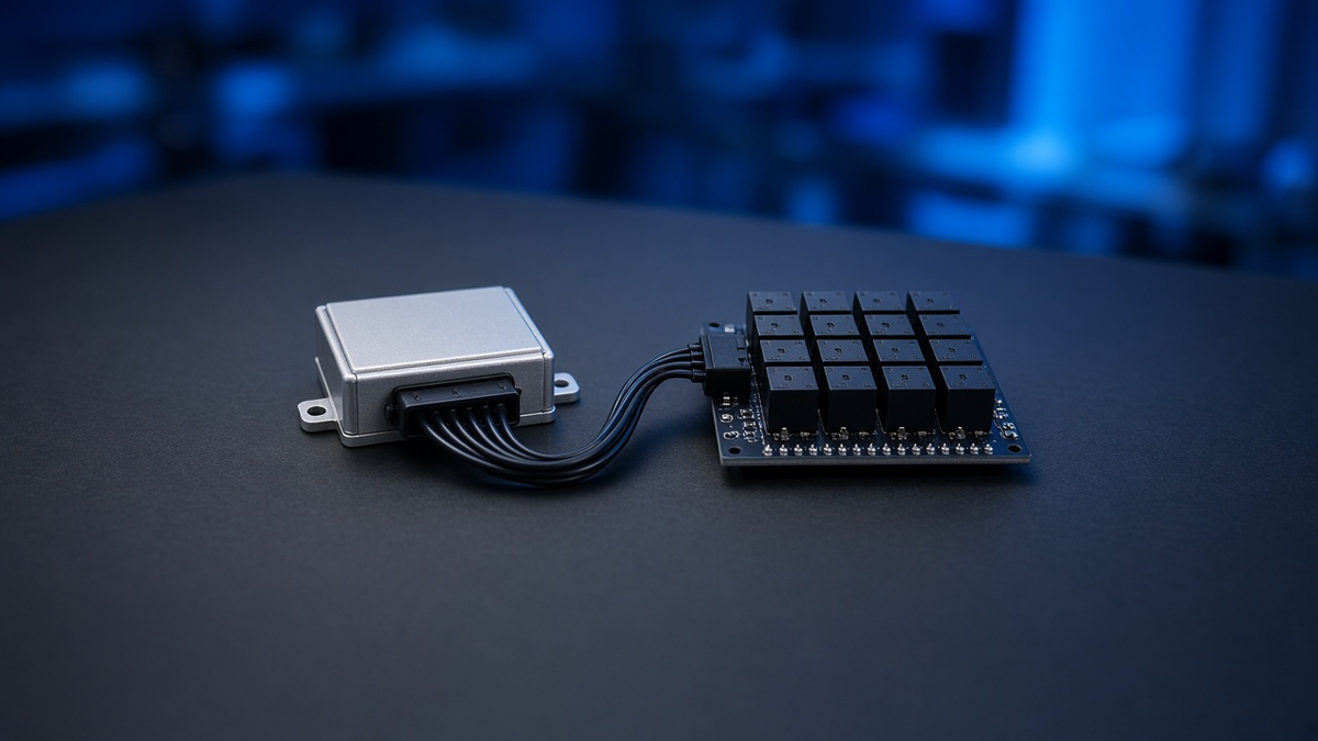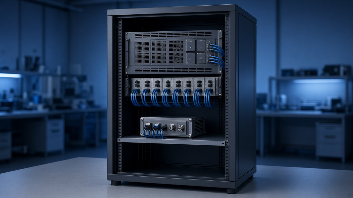


An intermittent fault appears on one ECU input, only when the engine fan starts. The quickest way to see it is to put a probe on that pin while the system runs, but the pin is buried in a sealed 60-way connector, and back-probing it risks damaging the seal or shorting two contacts. A breakout box solves this: it sits between the harness and the ECU, passes every signal through, and brings each one out to a socket where you can measure, monitor, interrupt or inject, without cutting a single wire.
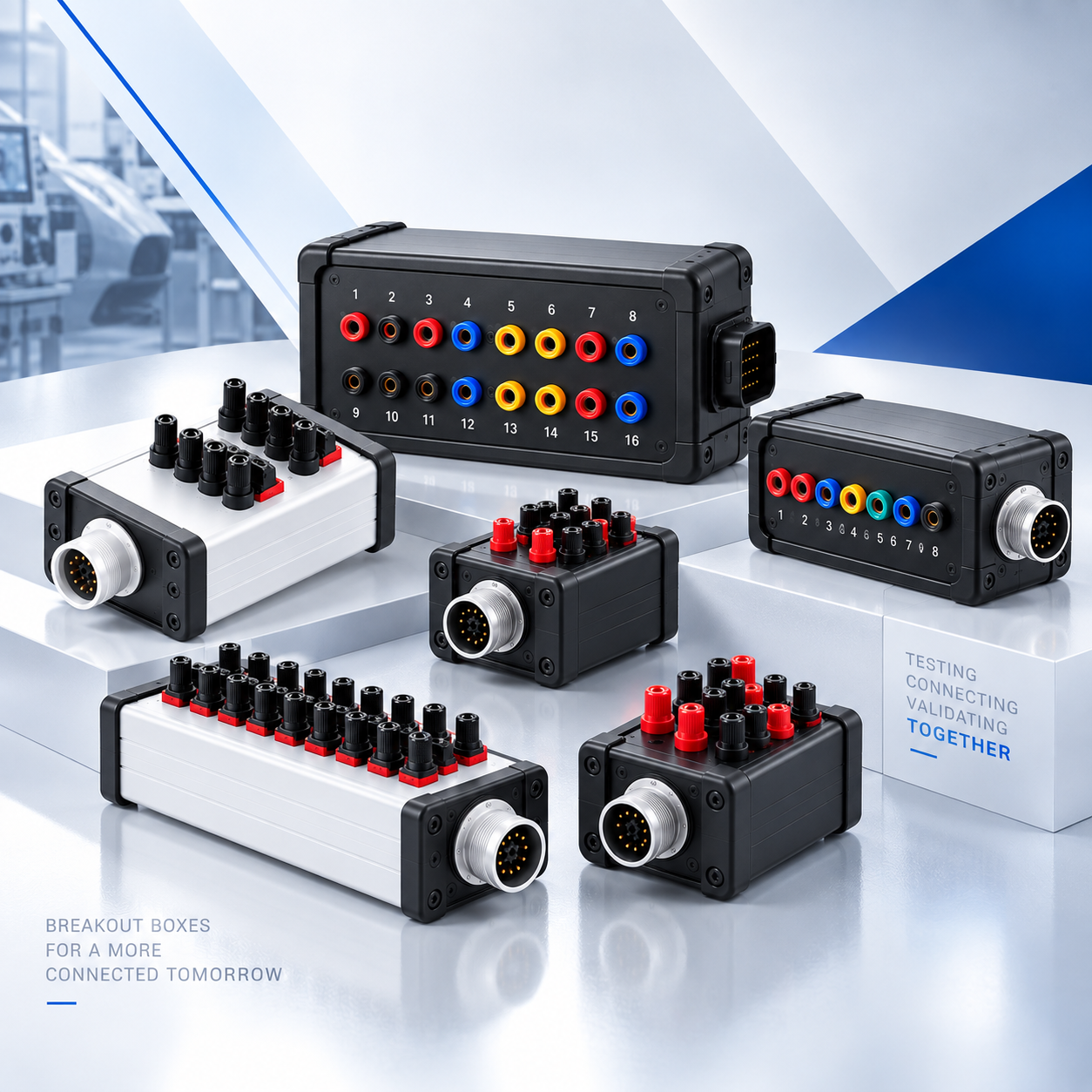
This guide explains what a breakout box is used for and, above all, how to write a specification that gives you the right box the first time.
1. What a breakout box does
1.1 Principle diagram (described)
Picture a box with two mating connectors, A and B, of the same type as the ECU interface. Connector A receives the harness; connector B goes to the ECU (directly or through a short adapter cable). Inside, each line goes from A to B through:
- a measurement socket (typically a 4 mm or 2 mm socket, shrouded where voltage or energy requires it) tapping the line;
- optionally a link or switch in series, so the line can be opened and bridged externally;
- optionally a second socket on the ECU side of the link, so you can insert a meter in series to measure current or inject a signal.
With no link removed, the box is electrically transparent, apart from the small resistance of its internal wiring and contacts.
1.2 Typical uses
- Measurement: voltage on any pin with a multimeter or oscilloscope, while the system runs.
- Signal monitoring: watching a sensor, PWM output or bus line during a test sequence.
- Interrupting a line: opening a link to simulate a disconnected signal.
- Bridging or rerouting: connecting a line to a different source, or to a lab instrument.
- Injection: feeding a signal from a generator or a simulator into the ECU.
- Current measurement: inserting an ammeter in series through the two-socket arrangement.
Breakout boxes are basic tools in development labs, HIL benches and diagnostics. For automated, repeatable disturbances, the same position in the chain is used by a fault-injection matrix (Fault injection on harnesses and ECUs).
2. How to specify a breakout box
A vague request such as “a breakout box for our ECU” leads to back-and-forth. The following points are what an engineer needs to design the box.
2.1 Connectors
- Exact connector references on both sides, including the mating half, the keying/coding and the gender. The box usually needs the counterpart of each side: what plugs into the harness and what plugs into the ECU.
- Number of ways and which positions are actually populated.
- Multiple connectors: many ECUs have two or three connectors; decide whether one box covers all of them or one box per connector.
- Mating cycles: a breakout box is connected and disconnected far more often than a vehicle connector. Consider sacrificial adapter cables to protect expensive ECU-side connectors.
2.2 Current and voltage per line
- Maximum continuous current per line and peak current (inrush of loads).
- Maximum voltage present on any line, including transients if the box stays connected during load-dump or cranking tests.
- Lines that carry power (supply, high-side outputs) need heavier internal wiring and sockets rated for that current. Do not assume one rating for all lines.
2.3 Measurement sockets
- Socket type: shrouded safety sockets for any line that can carry significant energy, compact sockets where density matters.
- Colour coding: for example red for supply, black for ground, another colour for signals, agreed in advance.
- Layout: logical order (by connector position) so the operator can find pin 37 without counting.
2.4 Grounds: the most underestimated point
ECUs often have several ground pins (power ground, sensor ground, digital ground) that share the return current. If the box merges them, or adds unequal resistance to them, the current distribution changes and sensor readings shift.
Example (illustrative values): an ECU returns 10 A through two power-ground pins. In the vehicle each path is about 20 mΩ, so each carries about 5 A. If the box adds 30 mΩ to one path only, that path becomes 50 mΩ, and the current divides inversely to resistance: about 10 × 20/(20+50) ≈ 2.9 A in the longer path and 7.1 A in the other. The pin carrying 7.1 A now carries about 40 % more than its nominal 5 A share, and the ground offset seen by the ECU changes. Rule: keep each ground pin on its own path, with equal and low resistance, and state in the specification how many return pins exist and how much current each carries.
2.5 Voltage drop added by the box
Example (illustrative values): internal wiring of 0.5 m (go and return 1 m) of 0.5 mm² copper, about 36 mΩ/m, plus two contact pairs of 5 mΩ each: about 36 + 10 = 46 mΩ. At 5 A this drops 0.23 V. For a power line, that may matter for undervoltage thresholds; for a sensor signal at a few milliamps it is negligible. Specify which lines are sensitive.
2.6 Protection of measurement equipment
A breakout box gives direct access to energised lines. Depending on use, specify:
- series resistors on measurement sockets (limits current if a probe slips, but adds error for loaded measurements);
- fuses on power lines;
- filtering if signals must be observed in a noisy environment;
- clear marking of lines that can carry dangerous voltage.
These features are trade-offs: a series resistor protects the line but distorts measurements made with low-impedance instruments. State the use case and let the design follow. Breakout boxes on 12/24 V vehicle lines are not mains-rated equipment; do not use them on high-voltage systems unless designed for it.
2.7 Mechanical and environment
- Bench use or in-vehicle use (size, cable length, robustness, fixing).
- Housing material and closing method.
- Cable length between box and ECU: longer cables add resistance and capacitance (relevant for buses and fast signals).
3. Documentation: the pinout table
A breakout box without documentation is a box of anonymous sockets. Each box should be delivered with a pinout table:
| Socket label | Connector / pin | Signal name | Type | Max current | Notes |
|---|---|---|---|---|---|
| 1 | A-1 / B-1 | Supply (example) | Power | 10 A (example) | Fused |
| 2 | A-2 / B-2 | Sensor ground (example) | Ground | 1 A (example) | Separate path |
Values in this table are examples; real ratings come from the specification of each box.
The labels on the front panel should match the table exactly. When the box is used on a bench, this table feeds the bench wiring list and its continuity check (Wiring harness testing: continuity, short circuit and insulation).
4. Common mistakes
- Specifying the ECU connector but not its mating half or coding.
- One current rating for all lines, including power lines.
- Merging ground pins in the box.
- Measurement sockets with no logical order or with labels that differ from the documentation.
- No adapter cable, so the ECU connector wears out after a few weeks of daily use.
- Long cables to the ECU on CAN or fast lines, without checking the effect.
5. Specification checklist
- [ ] Connector references (both sides, mating halves, coding, gender)
- [ ] Populated positions and signal list
- [ ] Max continuous and peak current per line
- [ ] Max voltage including transients
- [ ] Number of ground return pins and current per pin
- [ ] Socket type, colour code, layout
- [ ] Series links / switches required on which lines
- [ ] Protection (series resistors, fuses, filtering) and on which lines
- [ ] Bench or in-vehicle use, cable lengths
- [ ] Pinout table and panel labelling
Breakout boxes at RAYNOV
RAYNOV designs and builds breakout boxes in several pin counts; the current range is listed in our breakout box catalogue, and the full list of equipment is on the products page. For a box tailored to a specific ECU interface, or integrated into a larger bench (HIL test benches: architecture, components and implementation steps), see our custom validation systems.
Further reading
- Wikipedia, Hardware-in-the-loop simulation: context on where breakout access is used in HIL testing.
Need a breakout box for a specific ECU or harness? Send us your connector list.