
The connectors arrive, the contacts arrive, the harness is ready to build, and the first contact will not go into the cavity. It is a pin; the connector needs sockets. Or it fits, but the wire chosen in the design is one size too large for the contact barrel, and the crimp either cannot close or closes on half the strands. These mistakes are not exotic. They are the most common causes of lost days in harness manufacturing, and almost all of them are decided before anyone picks up a crimp tool: at the moment the bill of materials is written.
This guide goes through the choices that make a connector, its contacts, the wire and the tool compatible, and the checks that catch a mismatch before ordering.
1. Contact gender follows the connector, not habit
A common reflex is “the harness side gets sockets, the equipment side gets pins”. Sometimes that is true; often it is not. In many circular and automotive connector families, the insert or housing is designed for one contact gender, and the gender of the contacts is fixed by the connector part number.
- Read the gender from the connector datasheet, for the exact part number, not from the mating side.
- Check both halves: a plug can carry pins or sockets depending on the variant, and the receptacle must carry the opposite.
- For safety, the side that stays live when disconnected usually carries the protected (socket) contacts. This is a design rule to agree, not an assumption to make.
2. Contact size determines the wire range
2.1 Barrel size and wire section
Each contact is designed for a range of wire sections (in mm² or AWG) and often a range of insulation outer diameters for the insulation crimp or the seal. Outside that range:
- Wire too large: strands do not fit the barrel, or the crimp is over-compressed and strands are cut. Some strands may be left outside.
- Wire too small: the crimp does not compress the conductor enough; the joint looks fine but has high resistance and low pull-out force.
- Insulation too thick or too thin: the insulation crimp or the individual wire seal does not grip or seal correctly, which matters in sealed automotive connectors.
2.2 Worked example: choosing the wire before the contact (illustrative values)
Start from the electrical need, then check that a contact exists for that wire.
Example: a load draws 8 A at 12 V through a 3 m wire (6 m go and return if the return is also a wire). You allow a 0.3 V drop. Required resistance: R = 0.3 / 8 = 0.0375 Ω for 6 m, so 6.25 mΩ/m. With copper at about 0.0175 Ω·mm²/m, the section is S = 0.0175 / 0.00625 ≈ 2.8 mm². A 0.75 mm² wire, which might seem “enough for 8 A” thermally, would drop about 0.0175 × 6 / 0.75 × 8 ≈ 1.1 V. The voltage-drop requirement, not the current alone, drives the section here.
The next standard section is 4 mm² (about 0.21 V drop); 2.5 mm² would give about 0.0175 × 6 / 2.5 × 8 ≈ 0.34 V, above the 0.3 V limit. Only then check: does the chosen contact accept 4 mm²? If the drop limit can be relaxed to about 0.35 V, 2.5 mm² becomes possible; that is a design decision, not a rounding. If the connector family’s contacts for that cavity size stop at a smaller section, the options are a larger contact size (if the connector has such cavities), splitting the current over two contacts (with care: unequal sharing), or a different connector. This is why wire and contact must be chosen together.
2.3 Current rating of the contact
The contact’s current rating is usually given for a specific wire section, ambient temperature and number of loaded contacts. In a densely loaded connector, the allowable current per contact is often derated. Use the manufacturer’s derating curve for the actual configuration; do not reuse a single-contact rating.
3. Materials and plating for the environment
- Contact plating: gold is commonly chosen for low-level signals and low contact forces because it resists oxidation; tin is common for power and general use. Mixing gold-plated and tin-plated mating contacts is usually discouraged by manufacturers because of galvanic and fretting effects. Follow the connector manufacturer’s recommendation.
- Housing material: plastic or metal shells, with different resistance to temperature, fluids, vibration and, for metal shells, shielding continuity.
- Sealing: sealed connectors rely on wire seals or grommets sized to the insulation diameter, cavity plugs for empty positions, and an interface seal. An unplugged empty cavity is a leak path.
- Temperature: check the operating range of the housing, contacts and the wire insulation together; the weakest one sets the limit. Include the self-heating of the contact under current.
4. The crimp tool is part of the specification
4.1 Dedicated tool, right die, right setting
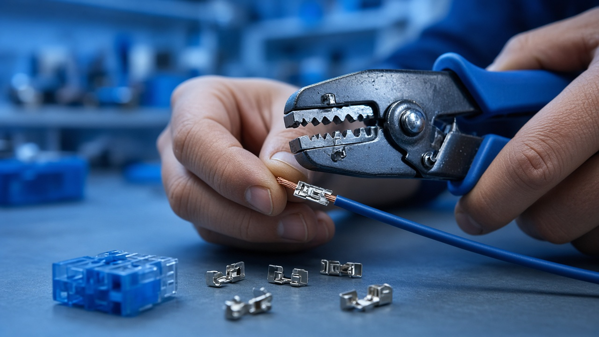
A crimp is a controlled deformation defined by the contact manufacturer for a given tool and die. Using a “similar” tool gives a crimp that may look acceptable and fail later.
- Use the tool and die (or locator/positioner) specified for the contact and wire section.
- For tools with settings (selector for wire size), the setting is part of the work instruction.
- Machined contacts (common in circular connectors) and stamped-and-formed contacts (common in automotive) use different tool types; they are not interchangeable.
4.2 Tool condition and control
- Tools wear. A tool that has been dropped or used beyond its life can under-crimp.
- Control the tool periodically with gauges or the manufacturer’s method, and check with pull tests on samples at the start of a batch and after changing the tool, die or contact reel.
- The minimum pull-out force is given by the contact manufacturer; record the result (Wiring harness testing: continuity, short circuit and insulation).
4.3 What a good crimp looks like (visual criteria)
- Conductor visible in the inspection window (or just past the barrel, depending on contact design), with no strands outside.
- Insulation crimp holding the insulation, not the conductor.
- Correct bellmouth, no cracks in the barrel, no bend at the contact.
- Insulation not trapped in the conductor crimp.
The IPC/WHMA-A-620 standard, published by IPC, is widely used as a reference for these criteria; the manufacturer’s application specification for the contact remains the primary source.
5. Every character of the part number matters
Connector and contact part numbers encode the shell size, insert arrangement, contact gender, keying, plating, finish and sometimes the wire range. Two numbers that differ by one letter can describe:
- a pin version and a socket version;
- two keying positions that will not mate;
- two platings;
- two wire ranges for the same contact size.
Practical rules:
- Copy part numbers from the datasheet ordering code, not from memory or from a previous order.
- Decode each field of the ordering code in the BOM review, line by line.
- Check that the contact part number is listed as compatible with the exact connector part number in the manufacturer’s documentation.
- When an equivalent is proposed, verify each field again: same contact size, same wire range, same gender, compatible plating, same keying.
6. Worked review: a typical BOM line (illustrative)
Example of a review, not a real project: a BOM lists a circular connector receptacle, socket contacts, and 1.5 mm² wire for a 10 A supply.
- Connector datasheet: this receptacle variant takes pin contacts. The socket contacts are wrong. → Change to pin contacts, or change the receptacle variant if sockets are required on this side for safety.
- Contact size for the supply cavities: rated for a wire range that ends below 1.5 mm². → Choose a larger contact size cavity if available in the insert arrangement, or revise the wire section after checking voltage drop.
- Plating: mating plug uses gold contacts; proposed contacts are tin. → Align plating with the mating half.
- Tool: the BOM has no crimp tool line. → Add the specified tool, die/positioner and pull-test reference.
Four lines, four issues, none visible on the drawing.
7. Common mistakes
- Choosing contact gender by habit instead of the connector part number.
- Choosing wire section for current only, ignoring voltage drop and the contact’s wire range.
- Using a single-contact current rating in a fully loaded connector.
- Mixing contact platings across mating halves.
- Crimping with a “close enough” tool or die.
- Ordering from a part number copied from an old order with one letter different.
- Leaving empty cavities in a sealed connector without plugs.
8. Pre-order checklist
- [ ] Connector part number decoded field by field
- [ ] Contact gender confirmed from the connector datasheet
- [ ] Wire section justified (current, voltage drop, temperature)
- [ ] Contact wire range and insulation diameter compatible with the wire
- [ ] Current rating checked with derating for the real configuration
- [ ] Plating compatible with the mating half and the environment
- [ ] Seals and cavity plugs for sealed connectors
- [ ] Crimp tool, die/positioner and pull-test minimum identified
- [ ] Any proposed equivalent re-checked on every field
From contact selection to a tested harness
Correct contact selection is the first step of a harness that will pass its electrical checks and survive in service. It also matters for test equipment: breakout boxes and bench harnesses use the same connectors as the device under test and are mated far more often (Breakout boxes: what they are for and how to specify one). RAYNOV handles harness design and manufacturing in-house as part of its custom validation systems.
Further reading
- Wikipedia, Crimp (electrical): general background on crimp joints.
- IPC: publisher of IPC/WHMA-A-620.
Reviewing a connector BOM or need prototype harnesses? Talk to our team.