

A BMS passes every functional test on a HIL bench, then in the first pack trials it reports a cell imbalance that does not exist. The culprit is not the software. The cell emulator channels drift by a few millivolts with temperature, and the BMS, whose job is precisely to see millivolts, sees them. On a body controller, a few millivolts of error on an input is irrelevant. On a battery management system, it is the measurement.
That one example captures most of what changes. A BMS is an ECU, and much of classic ECU validation still applies: requirements, test levels, fault injection, bus communication, diagnostics. But the physics it watches, the accuracy it needs and the energy around it are different enough that a bench designed for a classic ECU will mislead you if it is reused as is.
1. What a BMS actually does
A battery management system has five core jobs:
- Measure: every cell voltage (often in series stacks of many cells), pack current, several temperatures, and the high-voltage bus and insulation resistance.
- Estimate: state of charge (SOC), state of health (SOH) and available power, from those measurements and a model of the cell. See state of charge and Coulomb counting for background.
- Protect: open contactors or limit current on over-voltage, under-voltage, over-current, over-temperature and insulation faults.
- Balance: equalise cell charge, usually by bleeding energy from the highest cells through resistors (passive) or moving it between cells (active).
- Communicate: report limits and status to the vehicle or system controller, and manage pre-charge and contactor sequences.
A general overview is given in the article on battery management systems.
2. Principle diagram of a BMS test bench (described)
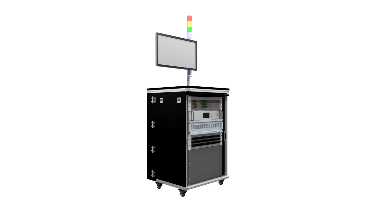
Picture the BMS in the centre. On its left, a stack of cell emulators: one isolated, programmable voltage source per cell, stacked in series so the BMS sees the same common-mode voltages as in a real pack. Each channel can source and sink current, because balancing draws current from the cell. Next to them, temperature emulators (programmable resistances replacing the NTC thermistors).
Below the BMS, a current sensor emulation path: either a shunt signal or a Hall sensor output generated by the bench, or a real current through a real sensor driven by a bidirectional power supply.
On the right, the high-voltage side: pack voltage emulation, contactor coils and auxiliary contacts, a pre-charge circuit, and an insulation fault injector (switchable resistors between HV+ or HV− and chassis).
Above, a real-time target runs the cell and pack model (open-circuit voltage vs SOC, internal resistance, temperature) and commands every emulator, while the host PC runs the test sequences. Around the whole HV part, a physical barrier, interlocks and an emergency stop.
Compared with a classic ECU HIL bench (see the HIL bench architecture guide), three blocks are new: the cell emulator stack, the HV and insulation section, and the safety envelope.
3. What changes, point by point
3.1 Accuracy moves from volts to millivolts
On a classic ECU, an analog input tolerance of tens of millivolts is often acceptable. A BMS estimates SOC partly from cell voltage, and on many lithium-ion chemistries the open-circuit voltage curve is very flat in the middle of the SOC range.
Worked example 1: what a millivolt is worth.
Example (illustrative values, not RAYNOV specifications).
Assume an LFP-type cell, whose open-circuit voltage changes by only about 100 mV between 20 % and 80 % SOC, roughly linearly (illustrative; NMC cells typically change several times more). The slope is:
100 mV / 60 % SOC ≈ 1.7 mV per % SOC
A bench channel error of 5 mV is then equivalent to:
5 / 1.7 ≈ 3 % SOC
So a bench that is “accurate to 5 mV” can by itself shift a voltage-based SOC estimate by about 3 %. On the LFP plateau the slope is even flatter locally, so the effect is larger; on NMC it is several times smaller. Bench accuracy must be specified relative to the BMS accuracy you are trying to verify, with a margin. As with any measurement chain, a test-accuracy ratio rule of thumb applies; the guide on acquisition timing and windows discusses similar ratios.
Two consequences:
– each cell emulator channel must be calibrated, and its drift with temperature checked, not only its accuracy at 23 °C;
– the cell emulators must stay accurate while the BMS loads them with balancing current, which a plain voltage source may not do.
3.2 Common-mode voltage and isolation
Cell voltages are measured on top of a large series stack. The top cell of the stack sits at the full pack voltage relative to the bottom. The emulator channels must therefore be isolated from each other and from earth, rated for the full stack voltage plus margin, and stable when the stack is switched, pre-charged or disturbed.
3.3 Balancing needs current, not only voltage
Worked example 2: passive balancing current.
Example (illustrative values, not RAYNOV specifications).
A passive balancing resistor of 33 Ω across a cell at 3.7 V draws:
I = V / R = 3.7 / 33 ≈ 0.11 A
and dissipates:
P = V² / R = 3.7² / 33 ≈ 0.41 W
Each emulator channel must sink this current while keeping its voltage within tolerance. To verify balancing, the bench must also measure that current, or the voltage response of the emulated cell, to confirm that the BMS switched the right cell at the right time. If 12 cells balance at once on one board, the dissipation on the BMS is about 12 × 0.415 ≈ 5 W, which is a thermal test case in its own right.
3.4 Estimation algorithms need long, realistic profiles
A classic ECU test can often check a function in seconds. SOC and SOH estimation only shows its errors over hours: drift of the current integration, recalibration at rest, temperature effects.
Worked example 3: current-sensor offset drift.
Example (illustrative values, not RAYNOV specifications).
A current-sensor offset of 0.2 A, integrated over 10 hours, gives a charge error of:
ΔQ = 0.2 A × 10 h = 2 Ah
On a 100 Ah pack, that is 2 % SOC of error accumulated by Coulomb counting alone, before any correction. A test that wants to verify the BMS correction strategy must therefore inject known offsets on the emulated current and run long enough, with rest periods, to see the correction act. This argues strongly for running the cell model on a real-time target and for a fully automated sequencer that can run unattended overnight (see the guide on moving from scripts to a sequencer).
3.5 High voltage and safety are part of the bench, not an option
Many BMS functions involve the high-voltage side: pre-charge, contactor control and welding detection, insulation monitoring. Testing them means real or emulated high voltage on the bench. That brings:
- physical protection: barriers, interlocks on access doors, an emergency stop that de-energises all sources;
- qualified and authorised personnel for HV work;
- appropriate HV PPE and insulated tools;
- a lock-out/tag-out (LOTO) procedure;
- discharge paths and verification of absence of voltage before access;
- fault injection designed for HV (switching, insulation, creepage and clearance of relays and connectors).
Worked example 4: pre-charge time.
Example (illustrative values, not RAYNOV specifications).
A pre-charge resistor R = 50 Ω charges a DC-link capacitance C = 1 mF. The time constant is:
τ = R × C = 50 × 0.001 = 50 ms
To reach 95 % of the pack voltage takes about 3τ = 150 ms. If the BMS closes the main contactor after a fixed 100 ms, the voltage across it is still about e^(−2) ≈ 13.5 % of the pack voltage, which may create an inrush the contactor is not rated for. In practice, the main contactor is closed only once the DC-link voltage has reached a defined threshold, typically 90–95 % of the pack voltage (about 3τ here), confirmed by measurement rather than by a fixed delay. Closing at about 86 % (2τ, the 100 ms case above) is a test case to detect, not an acceptable design. The bench must therefore emulate a realistic DC-link capacitance and measure the voltage at the moment of closing, and test cases must include a larger capacitance (aged or different inverter) to check the BMS logic.
3.6 Insulation monitoring
The BMS, or a dedicated monitor, measures the insulation resistance between the HV bus and chassis. Testing it needs switchable, calibrated resistances from HV+ and HV− to chassis, with the right voltage rating, and test cases on symmetric and asymmetric faults. This is fault injection, as described in the fault injection guide, but in a voltage range where relays, wiring and measurement need HV ratings.
3.7 Thermal behaviour and the thermistor chain
Temperature measurements usually come from NTC thermistors. Emulating them means programmable resistances with enough resolution near the protection thresholds, where an NTC’s resistance changes fast. Test cases should cover open and shorted sensors, because a BMS must detect a lost temperature reading rather than read it as “very cold” or “very hot”.
3.8 From BMS to pack
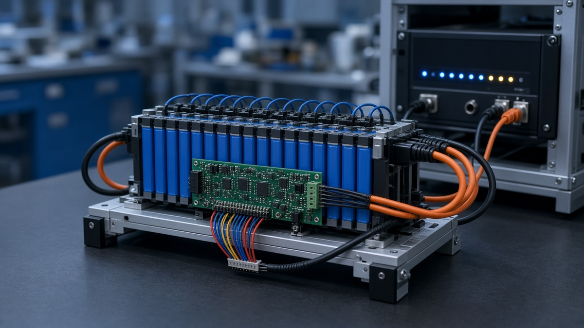
Testing a full pack adds real cells, real energy and real thermal mass. Charging and discharging cycles need a bidirectional power source, thermal chambers, and protection against thermal runaway. At pack level, harness quality matters too: sense wires to every cell are long and many, and continuity and insulation must be checked (see the guide on harness continuity and insulation testing).
4. Selection criteria for a BMS test bench
- Number of cell channels and maximum stack voltage.
- Channel accuracy and stability over temperature, compared with the BMS accuracy to verify.
- Source and sink current per channel (balancing), and response time.
- Isolation rating between channels and to earth.
- Current emulation: range, resolution, offset control, polarity.
- Temperature emulation: resistance range and resolution near thresholds.
- HV section: voltage rating, insulation fault injection, DC-link emulation, contactor feedback.
- Real-time model of the cell and pack, and automation for long profiles.
- Safety concept: barriers, interlocks, emergency stop, discharge, HV PPE, lock-out/tag-out, procedures. Standards such as ISO 6469-3 (electrical safety of electrically propelled vehicles) and EN 50110 (operation of electrical installations) are useful references for the safety concept.
- Breakout access to all low-voltage signals, for example through a breakout box.
For BMS interface, communication and fault-injection work on the low-voltage side, a compact bench such as the Mini HIL test bench can be a starting point; HV and cell-emulation sections are specified separately.
5. Common mistakes
- Reusing an ECU HIL bench without checking the analog accuracy. The bench becomes the main source of SOC error.
- Emulating cells with sources that cannot sink current. Balancing tests become meaningless.
- Short test profiles only. Estimation drift never appears.
- Ignoring common-mode voltage. Non-isolated channels or under-rated isolation create measurement errors or hazards.
- Fixed, ideal DC-link capacitance. Pre-charge logic is never stressed.
- Treating HV safety as a procedure only. It must be designed into the bench and verified during bench qualification (see the FAT and SAT guide).
- Testing the thermistor values but not the sensor faults. Open and short circuits on NTC lines are classic field failures.
6. Checklist: BMS validation campaign
- [ ] Cell emulator accuracy specified against BMS voltage accuracy, with margin.
- [ ] Channel calibration and temperature drift checked.
- [ ] Source and sink capability verified at the balancing current.
- [ ] Isolation rating checked for the full stack voltage.
- [ ] Current offset and gain errors injectable; long profiles with rest periods planned.
- [ ] NTC emulation, including open and short faults.
- [ ] Pre-charge tested with nominal and worst-case DC-link capacitance.
- [ ] Insulation faults injected on HV+ and HV−, symmetric and asymmetric.
- [ ] Contactor feedback and welding detection tested.
- [ ] HV safety concept in place: barriers, interlocks, emergency stop, qualified staff, HV PPE, lock-out/tag-out.
- [ ] Acceptance and qualification test plans separated (see ATP vs QTP).
7. Conclusion
A BMS is an ECU, but a demanding one. Its validation needs millivolt-level emulation that can also sink current, long automated profiles to expose estimation drift, and a high-voltage section with safety designed in. Start from classic ECU validation practices (test levels, fault injection, automation), then add the three blocks a battery requires: accurate cell emulation, HV and insulation, and the safety envelope. For the broader background on cell chemistry, see the overview of the lithium-ion battery.
Preparing a BMS or battery pack validation campaign? Request a quote from RAYNOV and our engineers will review your test requirements with you.